Production of thermal energy
Production of thermal energy Local heat production. Local heating is produced in separate fireboxes separately for each room. The following are distinguished: fireplaces, stoves with high heat accumulation, stoves with low heat accumulation and furnaces for heating with oil, gas or electricity.
Fireplaces are the oldest open-hearth heating stoves. The room is heated mainly by heat radiation. The degree of utilization of this heating is only 10 to 15%, since most of the heat is extracted through the flue gas through the chimney. Heating with a fireplace achieves good ventilation but insufficient room heating. Fireplaces are rarely used today, only for additional heating and sometimes for decoration (decoration).
Tile stoves are made of special ceramic tiles and clay bricks (or slabs) in shapes that are adapted to different conditions and requirements. The characteristic of these furnaces is that heat generation and heat transfer are time-shifted. Once or twice a firebox is ordered, which will burn out relatively quickly. In doing so, the released heat of combustion will be absorbed (accumulated) in the furnace walls. As the surface temperature of the furnace rises, the heat of the room is gradually released. The duration of heat dissipation depends on the thickness of the accumulation mass and the size of the outer surface of the furnace. Due to the large mass involved in the heat exchange, it is not possible to heat the room rapidly with these furnaces, nor are they suitable for the rapid regulation of heat transfer.
An iron furnace is a furnace with a cast iron or sheet steel sheath lined with fireclay on the inside to protect it from overheating. Regulation of heat emission in iron furnaces is achieved by regulating the air supply to the furnace, which accelerates or slows the combustion of fuel. Iron furnaces are suitable for both short-term and permanent operation. Iron furnaces are constantly being refined. The new endeavors seek to maximize the use of flue gas heat through a different way of managing them.
The gas furnace has the advantages of heating the premises with gas, compared to heating with solid fuels, such as: simple operation, quick heating and clean operation, waste fuel delivery and ash removal, temperature control can be automatic according to outside temperature, and the ability to accurately determine the consumption gas using a gas meter. The disadvantages are such heating: high operating costs, the risk of poisoning when the devices are defective and sometimes difficulties in the construction of the exhaust ducts for combustion gases.
The oil stove is heated with light fuel oil (fuel oil). The oil (free tank) flows from the free fall to the level-vessel with the float, where a constant (constant) oil level is maintained. From there, the oil flows through the control valve into the combustion chamber. After ignition, due to the effect of the heat of the flame, the oil evaporates, mixes with air, which is fed through the openings into the burner tank, and burned. The resulting combustion gases pass through the burner chamber around the heat exchanger or directly along the furnace outer shell into the gas outlet duct and into the chimney. The heated surfaces transfer heat to the room air, mainly by convection (flow) and only partly by heat radiation.
An electric furnace or electric heater is a device and an industrial electro-gas installation in which electricity is converted into thermal energy, and heat is used to obtain metals, heat and thermochemical treatment, and in general for baking, heating or drying, in industry, catering and household. In these devices, electricity is also used for heating by means of resistive heaters and for operating the refrigeration compressor.
Boilers in the general sense are a large closed cylindrical steel vessel in which water is heated and (or) evaporated by means of heat at constant pressure. The boiler is a large vessel used for water heating, steam production, distillation and the like. The fuel burns in the firebox. Exhaust gases circulate around the boiler heating surface and discharge into the chimney through a smoke duct (flue). The boiler is made in the form of a cylinder or as a combination of a cylinder, that is, drums and tubes. This combination increases the active surface of the boiler, through which heat flows from the exhaust gases to the water. The required combustion air is fed into the firebox by natural or artificial ventilation. The entry of fresh air into the firebox depends on the difference between the ambient pressure and the pressure in the firebox. If the pressure difference is produced only by the chimney, then it is natural ventilation, if it is produced by a fan, then it is artificial ventilation. Each boiler must have its own devices for proper operation and control of the proper operation of the boiler. These devices are called boiler fittings. The boiler armature includes: a safety valve that automatically releases excess pressure from the boiler as soon as it exceeds the permitted limit for which the boiler was built.
Watermark showing the height of the water in the boiler. Boiler feeder with water. Steam vent valve and boiler vent valve.
Steam boilers are boilers used for the production of water vapor, which are subsequently used by consumers, whether for heating, in heaters, or for propulsion in steam turbines and turbines. There are several types of steam boilers, different in appearance, purpose, pressure, temperature.
The first division of the boilers is according to the operating pressure into: low pressure (up to 7 bar), medium pressure (up to 22 bar), high pressure (over 22 bar).
By the type of water vapor they produce on boilers: wet steam, dry saturated steam, superheated steam. By the amount of steam produced on the boilers: low output or capacity, medium output, high output.
By its structural features we have a division into two basic groups: fire-tube boilers. In a fire-tube boiler, combustion gases pass through the pipes, and the water clogs the pipes and thus heats up. Such is a cylindrical or Scottish boiler, constructed in the form of a steel drum in which there is water, passing through it up to four corrugated pipes (burners) in which the fuel is burned. Except for steam boilers with one pass of flue gas, usually each burner ends with a flame or return chamber, from which many fire pipes (fire hoses) through the boiler direct the combustion gases into the smoke chamber at its front and continue into the chimney. There are also combined cylindrical boilers that have water pipes (Prudhon-Capus and Howden-Johnson boilers). Cylindrical boilers are of simple construction, insensitive to unclean water and easy to clean and are built for low pressures only. They are used on ships with steam jet machines and as auxiliary boilers on tankers. A water-tube steam boiler with water in the pipes and hot combustion gases around them can be made as a tube and a pipe. These boilers are nowadays used for more demanding applications, for example for the production of steam in transport, industry and energy, so more structures (Bensonov, La Montov, Löffler boiler and others) have been developed that differ in steam properties (with pressures even higher than 300 bar and vapor overheating temperatures and above 600 ° C), by capacity, by fuel, which may be coal, coal dust, liquid fuels, gaseous fuels, domestic, industrial or agricultural waste. In order to achieve the best possible energy conversion and to enable the steam plants to operate more reliably, additional components such as a steam superheater, water heater, and an air heater are connected to the boilers for greater effects.
Condensing boilers are high efficiency water heaters that are achieved by using waste heat to heat the water entering the boiler. The name of condensing boilers was given because the water vapor produced during combustion is condensed into the drained water. In many countries, their use is mandatory or financially encouraged.
Principle of operation: In a conventional boiler, combustion produces hot flue gases which, by passing through a heat exchanger, transfer most of their energy to water, as evidenced by the increase in water temperature. There is also water vapor in the flue gas that is produced by the combustion of hydrogen-containing fuels. The condensing boiler draws additional heat from the waste gases by condensing water vapor, which utilizes the residual evaporation heat. The usual increase in efficiency can be about 10-12%. The efficiency of this process varies depending on the temperature of the water returned to the boiler, but for the same conditions the efficiency is at least equal to the efficiency of the non-condensing boiler. The condensate produced is slightly acidic, pH 3-5, which affects the choice of material used where condensate is present. Aluminum alloys and stainless steels are used at high temperatures, and in low temperature areas the most cost-effective use of plastics, such as PVC and polypropylene. An additional heat exchanger must be installed to drain the residual condensation energy, which is the only difference with the non-condensing boiler. In order for the condensing boiler heat exchanger to be as economical in use as possible, the smallest possible size is required for its output energy.
The manufacturers of condensing boilers claim that a thermal efficiency of 98% can be achieved. Conventional models offer about 90% efficiency, which places most condensing boilers in the highest available category for energy efficiency. Boiler performance is based on heat transfer efficiency and largely depends on the size of the boiler and the exchanger. System performance and installation are critical. One of the reasons for the decrease in efficiency is the performance because the introduction of a heating system gives back water, which significantly prevents condensation in the heat exchanger. Manufacturers often cite the efficiency of condensing boilers above 100%.
Which is correct if the lower heating value of the fuel is taken into account to calculate the efficiency as energy released during evaporation, and the condensing boilers use the condensing energy to bring the energy used closer to the upper heating value of the fuel.
Heat pumps or heat pumps are systems of inexpensive and environmentally friendly heating, they can draw heat from water, earth or air. They work on a principle similar to refrigeration. The basic process that explains their work is the left-hand Carnot circular process. Heat pumps most often use freons as a cooling medium, but may use some other gases (eg ammonia). The simplest forms of heat pumps are air conditioners that heat and cool, so-called. inverters. They draw heat from the air, are the easiest to install and the cheapest. More complex forms that give more energy are systems that are dug underground, using the internal heat of the earth, which raises the temperature of the cooling medium (usually some of the freon gases). Heat pumps have not yet gained widespread use, although they are a better source of heating than fossil fuels that are slowly disappearing, polluting the environment and have a steady rise in prices.
A heat pump is a system based on a left-hand Carnot circular process that converts heat into a machine using ideal gas, usually some of the freons depending on the desired temperatures. The mode is almost identical to that of a home refrigerator, the difference being that the refrigeration unit takes heat away from the foodstuffs and delivers it to the environment while the heat pump takes heat from the air, water or earth, and brings it into the space we want to heat. The process consists of two adiabatic changes and two isothermal ones.
- The isothermal expansion of change takes place in a condenser that transfers the heat of the cooling medium to water or some other space that we want to heat. The refrigerant must go into the liquid phase.
- adiabatic expansion by a thermo-expansion valve within which the coolant loses pressure and decreases its temperature.
- the first isothermal change on the evaporator when it takes heat from the environment (water, soil, air) and the heated refrigerant in the vapor phase returns it back to the compressor, thus completing the cycle.
- adiabatic compression changes at the compressor where the pressure of the medium increases as does the temperature.
- the heating factor is an indicator of the energy efficiency of the heat pump operation, where the ratio of the heat output Qo and the external power supplied by the compressor W is the most important.

Parts of the heat pump: Compressor, Condenser, Thermal expansion valve, Evaporator. Compressors are machines that have the role of compressing the refrigerant, raising its temperature and pressure by bringing the work W. The condenser is a heat exchanger made as a pipe system into a coil where the refrigerant transmits heat. With heat pumps, it transfers its heat to the water that is heated and circulates through a water exchanger through a heat exchanger in the space where we heat, for example, the radiator, thus heating us. In cooling, it has a reverse role where it conducts heat. The expansion valve is a regulator of the flow of refrigerant through the system. It is located between the condenser and the evaporator. It enters the refrigerant from the condenser at higher pressure and higher temperature. When the gas exits the valve into a larger cross-section pipe, a lower cooling medium pressure is obtained. The expansion valve can be used to regulate the operation of the compressor by regulating the cross-sectional area at flow, its openness or closedness is regulated by a probe located on the suction pipe through which the coolant enters the compressor after the heat is transferred. Inside the probe is a medium (usually a fluid with a high coefficient of thermal expansion) that expands with the increase in the temperature of the coolant, thereby reducing the flow rate and resulting in a lower coolant temperature. In the opposite case, when the coolant is at a lower temperature, the valve opens and a slightly higher coolant temperature is obtained. By adjusting the valve opening, the compressor is optimally operated and the coolant temperature is optimized when the utilization is most favorable. Smaller systems do not use thermo-expansion valves but rather smaller pipes (capillaries) than pipes inside the system through which the refrigerant travels. The capillaries operate on the same principle, only in which the cross-sectional area of the gas flow is constant. An evaporator is a heat exchanger built as a system of tubes wound in a coil with a surface that enters the cooling medium at a lower temperature and takes heat from the ground, water or air. So to us, soil, water or air is the medium that transfers its energy to the heat pump. The evaporator is as functional as the condenser.
A solar hot water collector or solar collector is part of a solar hot water system, which directly converts solar energy into the thermal energy of water or some other working substance. Solar heating systems may be open, in which heated water flows directly through the roof collector (thermosiphon) or closed, where the collectors are filled with non-freezing fluid (glycol, antifreeze) and can be used at outside temperatures below 0 ° C. During a sunny day, the water can only be heated in the collectors, and if the weather is not nice, the collectors help to warm up, saving electricity. Solar collectors are very useful sources of thermal energy for swimming pool technology, where the water temperature is generally usable, and the optimal pool temperature is maintained for several weeks more in the year than without a solar hot water heating system. In the European Union, the amount of installed solar water systems for heating water and rooms is significantly increasing. During 2000, 1,046,140 m2 of new solar collectors were installed. Germany and Austria are European leaders in this solar heating technology. Thus, more than 60% of solar hot water systems were installed in comparison to the whole of Europe in Germany that year. The plan for the European Union was to install around 100 million m2 by 2010, but current indicators are around 80 million m2.
Solar hot water collectors can be: unconcentrated or concentrated. Unconcentrated solar collectors most commonly appear in the form of plate solar collectors. They are mainly used in heating and domestic hot water systems. They consist of a surface absorber, a working medium, a collector housing and a cover. The working medium of the converter can reach a temperature of about 200 ° C.
The simplest type of solar hot water collector is non-glazed collectors. As the name implies, such collectors do not have glazing or an insulated collector box, so they only consist of absorbers. The most common examples are do-it-yourself hot water tanks, which are facing the sun and painted black. The major disadvantages of such systems are the large losses of accumulated thermal energy (eg overnight or in cloudy weather) and the possibility of freezing the system in winter.
The plate solar collector has a degree of solar energy efficiency of 50-80%, and is a basic part of the solar hot water system. The collector is covered with solar glass and is resistant to hail and fracture. The collector tubes are laser connected to the collector copper sheet. The manifold can be mounted on a sloping roof, a flat roof or it can be fitted into the roof. The manifolds can be mounted on the roof up to an angle of 60 ° to the ground. The absorbers are coated with a high performance selective coating.
The collector frame is made of black anodized aluminum. It is recommended that they be dimensioned for summer hot water systems and installation angles of 20 – 30 °. Flat-panel solar collectors are high-temperature, structurally designed as flat panels and are used where the satisfactory temperature of the working substance (water) does not exceed 95 ° C, mainly for heating domestic hot water and swimming pool techniques. Medium temperature collectors are most commonly used indirectly for the production of hot water for residential and commercial use, and directly for cooking, disinfection and desalination. The collector itself is in fact a thermally insulated box with a single transparent side, which houses pipes through which water flows. The pipes feature sheet metal wings painted black. In this way sunlight enters through the transparent side and strikes the black tin surface and is converted into thermal energy. The sheet is heated, and as it is physically connected to the pipes, the pipes themselves are heated, thus heating the water that flows through them. The heated water is then discharged into a solar heat tank, where energy accumulates. If the solar system is located in a climate where in winter temperatures fall below 0 ºC, a mixture of antifreeze passes through the collectors instead of water. This mixture is then discharged into the tank, where it transfers energy to the inside of the tank using a heat exchanger. The cooled mixture is pumped back into the manifold where it is reheated.
For the needs of one household, a smaller solar hot water system is sufficient, consisting of 2 to 4 m2 of collector surface and a water tank of about 200 to 300 liters. However, it is worthwhile to install a larger system of, for example, 10 to 12 m2 of collector surface with a reservoir of 750 to 1000 liters. Such a system can accumulate enough energy in winter to connect to central heating, thereby reducing the heating bill. This type of heating is called active solar heating.
Solar equipment is still too expensive for the average person. High prices are probably the main reason why this technology is not being used to its full potential. In other countries, it is possible to get tax breaks when buying solar equipment, which is a miracle considering that the oil lobbies are extremely powerful and it is in no way in the oil industry’s interest that people use fossil fuels less. It is up to us in Croatia to fight for incentives to buy solar equipment. Combined with education, this technology could finally come to life. Another way to get around the costly problem is to build solar equipment on your own. Namely, people who know how to use basic carpentry tools can easily build their own solar system without much difficulty. This can save a huge amount of money, and the manufactured equipment does not necessarily have to be worse than the market.
A vacuum solar collector uses a similar mode as a thermos bottle (Dewar container). For the purpose of reducing thermal losses in the collector, the absorbers are contained in glass cylinders in which there is a vacuum, at a pressure of less than 0.01 bar. An absorber to be installed in vacuum tubes is a flat strip or coating applied to the inside of a glass vacuum tube. As the required surface area occupied by vacuum collectors is 1/3 smaller than flat collectors, they are suitable for roofs that do not have enough space for the installation of plate solar collectors. Vacuum solar collectors annually provide 5 – 8% more energy, and are used for winter water heating, and during the summer they can quickly overheat water to high temperatures over 130 ° C. The collectors have a high degree of absorption thanks to the aluminum nitrite coated absorber. Each collector tube can be individually replaced without draining the system. They are used in domestic hot water preparation systems and in heating assistance systems. They can be installed on sloping, flat roofs, and fitted into the roof. It is recommended that they be dimensioned for winter systems and installation angles of 50 – 60º. There are models of vacuum manifolds that can be built from the elements and a manifold that can hold up to 150 vacuum tubes can be built.
The basic difference between plate and vacuum collectors is in a different degree of utilization, depending on the season, and this difference arises from the dependence on the outside air temperature, which directly affects the efficiency of the collector. The plate collectors are better in the summer, while the vacuum ones are better in the winter. Vacuum collectors are much more expensive and are mostly used in the extremely cold climates of northern Europe. 80% of solar systems are used primarily for the preparation of domestic hot water, and such systems are sized for summer load. As plate collectors are planned for the summer, it is concluded that the only optimal choice is a plate collector for the area of Southeastern Europe, which has a relatively warm climate.
Annual solar radiation in Croatia is about 1600 kWh / m2 in coastal, up to 1100 kWh / m2 in continental Croatia. Solar collectors directly convert solar energy into thermal energy, and the conversion efficiency depends on the type of collector. As the outside air temperature decreases, the temperature difference between the collector and the outside air increases, and the overall efficiency of the collector decreases. The average annual collector efficiency is about 50 – 60% (about 500 – 800 kWh / m2 collector per year), while the system utilization rate is about 30-50% for a properly dimensioned system. In winter, the collector system gives the best effect in combination with underfloor heating, as temperatures between 40 and 50 ° C can be achieved in the collector, which will be sufficient for underfloor heating.
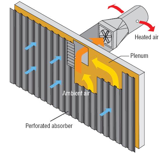
The solar wall is a solar air heating system, which is a specially designed solution and contains many internal and external parts. Uses solar energy to heat and ventilate indoor spaces in new and refurbished appropriate applications. The system design is tailored to ensure maximum energy delivery with the least amount of static pressure in the airspace. There are many forms of solar wall technology based on energy needs in buildings or according to customer needs. The most visible component of the system is the outer metal cladding, but a significant amount of solar wall equipment is found in the interior molded parts.
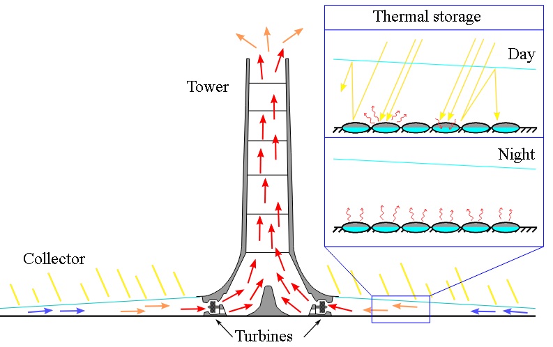
Concentrated Solar Power (CSP) is used in solar thermal power plants, where electricity is produced, usually on combined heat (with solar, they also have an additional source of fossil fuels, most often natural gas). In them, solar energy is first converted into thermal energy and then into electrical energy. Despite the fact that there are more links in this conversion process, their utilization rate is enviable (20-40%), and their negative environmental impact is negligible. Areas with many hours of sunshine (such as deserts and semi-deserts) are particularly suitable for the construction of such power plants.
There are currently several solar concentrating thermal power plants in the world. In these, by means of a mirror system (flat or parabolic) or lenses, combined with a system for monitoring the position of the sun in the celestial vault, direct solar radiation focuses on containers with some fluid (water, oil, liquid sodium, etc.) that is heated, and its passage through steam turbines or Stirling (heat) engines produces electricity. Very high temperatures are generated in this process, so these systems are also suitable for the production of heat and steam for other purposes (cogeneration). The use of such systems requires daily serenity, and in areas with significant cloud cover they have limited applicability.